Soundcube PCBs
For my fourth semester course "Digital Prototyping I" I designed an audio pcb. It can record and play audio, has many LEDs for visual feedback and two input methods for human control. Simple tactile switches and a magnetic rotary encoder.
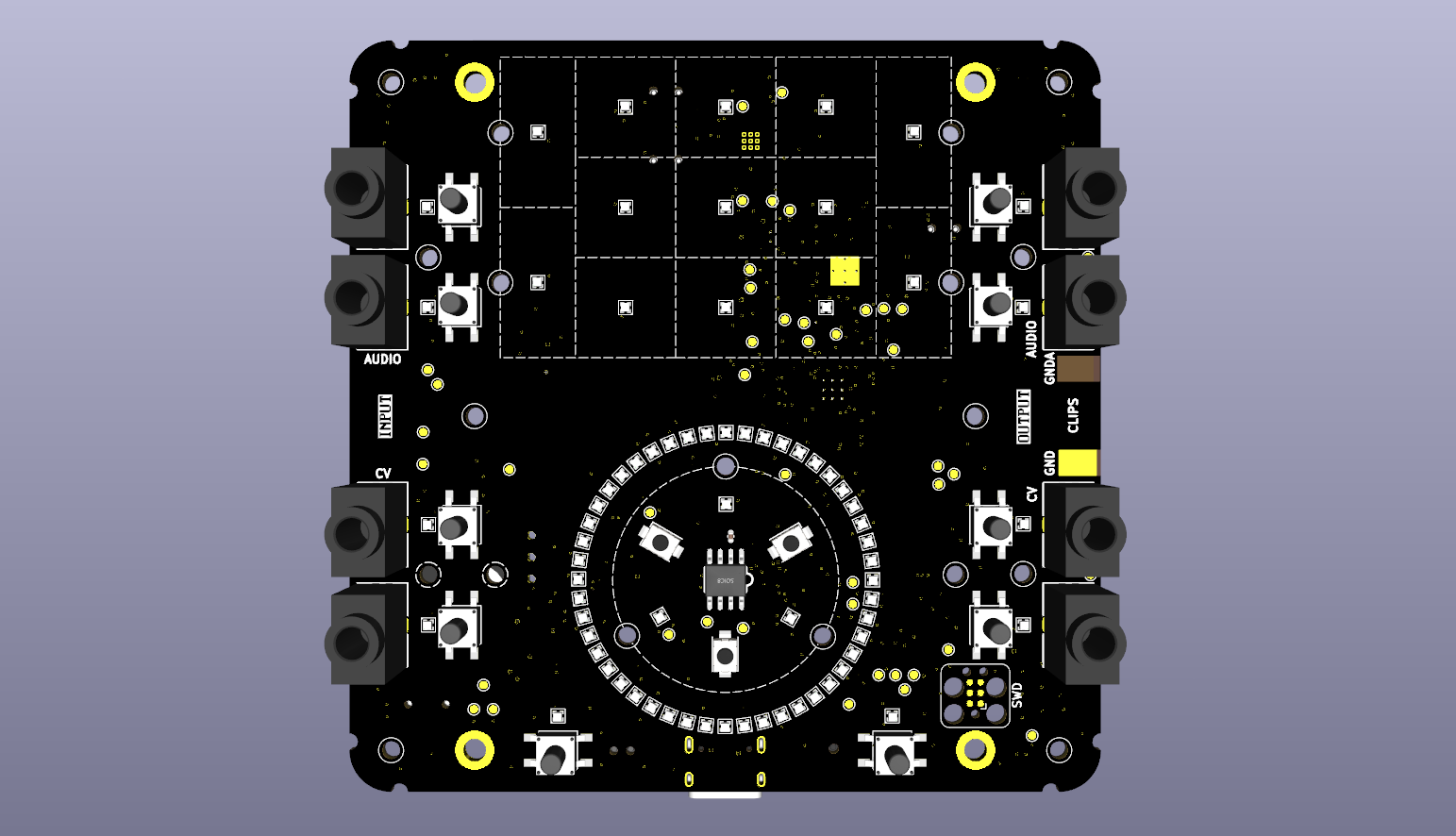
For my fourth semester course "Digital Prototyping I" I designed an audio pcb. It can record and play audio, has many LEDs for visual feedback and two input methods for human control. Simple tactile switches and a magnetic rotary encoder.
Hardware Design
The board is based on the RP2350 from Raspberry Pi, a nice little microcontroller with two cores running at 150MHz (or more) and the ability to attach 16Mb of PSRAM. Perfect for small and medium sized audio projects.
Sound
The audio codec is a TLV320AIC3204 from Texas Instruments. It has all the features and more for a board like this. The board uses one stereo input channel pair, headphone out and one stereo line out channel pair. Three SMD speakers found their way onto the board as well. Two of them are connected to a TP2012 stereo amplifier from Texas Instruments. The speakers can be switched on and off in software and mirror the audio on the line out jacks.
The other single speaker is connected via a AW8010AFCR from Shanghai Awinic Tech to a pin on the RP2350. It is used to generate PWM audio solely for interaction sounds. The idea was to have the audio for interaction not be audible on the line out and also work without using the main speakers.
Audio is routed from the line in jacks via AC coupling capacitors to the codec and from there using I2S to the RP2350. Audio generated in the RP2350 is then fed back over the I2S connection to the codec and from there via AC coupling capacitors to the line out jacks. It is also routed to a switch where the user can switch the source of the amplifier between the headphone out and the line out. The idea was that for future experiments one could maybe send multichannel audio to the codec and have separate channels play on the headphone out and the line out. But that was not tested.

SD Card
The initial idea for the PCB was to create a board that can do many things with audio and control voltage. To also make playback of samples possible I added an SD card slot which was also used by one group in the semester project. It is connected with full 4 line SPI is quite fast and worked great. The sampler group used it to load samples into PSRAM and that worked really well.
Control Voltage
Two channels of CV can be used in the firmware to control various things. At least in theory. The feature was not used in the project and also never really tested. The hardware side is implemented with two jacks as CV inputs that are routed straight to the ADCs on the RP2350. They are protected from overvoltage by clamping diodes and from overcurrent by a 1K resistor in line. The RP2350 has no DAC and for CV a PWM signal is not the best idea. For that reason I added a DAC8552 from the Burr Brown line of DACs from Texas Instruments. It is a 16 bit DAC with high quality and certainly a bit overkill, but why not? The outputs are routed through 100 Ohm resistors to the CV output jacks. The DAC is connected to the RP2350 by SPI. The CV level goes from 0V to 3.3V both at the input and the output side.
Power
The board is powered by the USB-C connector. It creates the necessary 3.3V for digital and analog signals on board using two TLV76733DRV from Texas Instruments. The analog side is separated as good as possible from all the digital noise. Much noisy stuff happens on the other side of the 6 layer board and is shielded by two ground planes from the analog audio side. It worked good enough but I really never tested its noise levels.
User Input
Every jack connector has a tactile switch and a tiny RGB led next to it. The function of these is free to define in software. Some projects used it to mute the corresponding channel. The most important feature is a magnetic encoder chip in the lower half of the board. It is also surrounded by tiny RGB leds. The idea was to have a rotary magnetic encoder as the main control element and the led ring as a visual feedback. Next to the encoder are two tactile switches with their own leds. The encoder itself can also be made pressable by three tacticle switches surrounding the chip and again leds to give visual feedback.

The encoder chip is an AS5600 from ams with 12 bit resolution. The leds are tiny 1mm by 1mm WS2812B RGB leds with integrated controller. Added for more lighting effects were 8 side facing WS2812B leds. Every led can be controlled independently and they all worked great. No flicker, no strange colors, nothing.
Display
There is no display on the pcb. For visual feedback it features the aforementioned leds but also a 13 led matrix made of a central 3x3 pattern and surrounding 4 leds. Most projects used the 3x3 matrix to signal modes of operation with either backlit plexiglas or with plexiglas extensions. The 48 led ring around the encoder was also used by every project for various purposes. Audio volume, speed of the sequencer, sample chosen, sequence placement etc.

Tactile Feedback
To make the interaction feel more nuanced I also added a quite large vibration motor to the board. It is switched on an off with a mosfet and can do nice things when driven by a PWM signal. It can be used to simulate tactile steps in the rotary encoder and also give a stronger tactile feedback when pressing a button.

The Board in Action
I ordered 25 boards at JLCPCB (after ordering 5 prototypes) and the quality and finish were great. Everything worked out of the box. The course was a cooperation between Prof. Janina Schmidt and me and the students did an amazing job designing their Sound Cubes. The students had to come up with ideas for musical devices that have the PCB as their foundation. They then had to draw flow charts of the interaction, think about the functions, develop parts of the firmware together with me and finally test and revise if something wasn't quite working.

More pictures and some more information here: Rundgang 2025